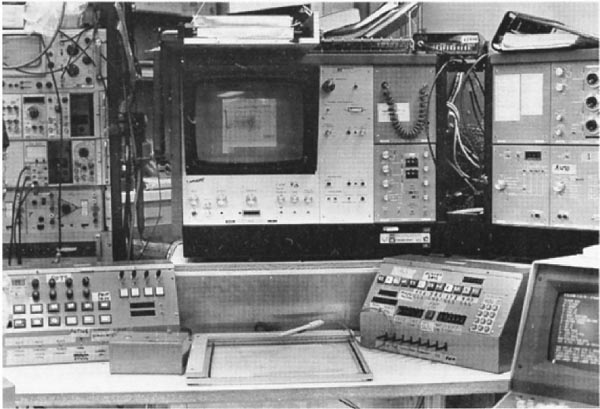
Figure 6. RTPP Control Console was interfaced to the PDP8e and used to interact with the RTPP using the BMON2 buffer memory monitor operating system [40, TR-21, TR-21b]. See Figure 2 in [TR-21b] for the full description. It had various knobs (connected to A/D converters read by the PDP8e), lights for feedback, command buttons, toggle switches, and momentary toggle switches. Only some of these controls were used in the various programs, but having a variety of control options providing flexibility in the user interface. However, this was sometimes at the cost of added complexity and sometimes users had difficulty in learning the system because of this. ("All those knobs, buttons and switches!") However, this flexibility gave us the option of experimenting with various interaction modes that could then be optimized for particular analysis programs. This was before the computer mouse and graphical user interfaces became commonly available. (Click on this figure to bring up the high-resolution version of the figure. You may have to make your browser window larger.)
Figure 8. Front of a buffer memory image card containing 64Kb x 16-bits of dynamic RAM constructed from 4Kx1 bit dynamic RAM chips (Texas Instruments part number TMS 4030) initially sold by Texas Instruments and later second-sourced by National Semiconductor and Signetics. Four boards constituted a 256x256x16-bit pixel sub-image. Either the high or low 8-bit byte (or neither) could be displayed. Each 256x256 sub-image could be positioned to any part of the 860x720 pixel TV screen. For many applications, to create a 512x512 image, four 256x256 sub-images were grouped to form a 512x512 image.
Figure 9. The 4Kx1 bit dynamic RAM or DRAM chip (part number TMS 4030) initially sold by Texas Instruments and second sourced by National Semiconductor, and Signetics (shown here). These were the first affordable (about $20 at the time) DRAMs available in large quantitities. Because chip vendors want to assure customers that the parts will always be available, they license other chip makers to "second source" interchangeable chips. Our memory boards are a mix of the black, silver, and gold colored chips because we used several vendors.
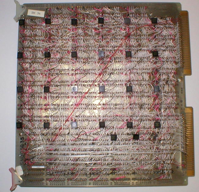
Figure 10. Back of a buffer memory image card containing 64Kb x 16-bits of dynamic RAM constructed from 4Kx1 bit dynamic RAM (part number TMS 4030) chips initially sold by Texas Instruments and second sourced by National Semiconductor and Signetics. There were over 3,000 wirewraps on each board. The initial card was designed and hand wired by George Carman, and Cambion Corporation replicated 63 additional cards with wirewrap wiring lists generated by George. Their automatic robots would position the board for each of the wrap positions and then wire that point. The photograph illustrates how easy it is to get lost in this forest of pins and wires. Doing this by hand would have been impossible. George felt that no other company could build the boards in the time frame with the essential quality control we required. He was right. Only one of the 63 the boards delivered was defective, which was amazing considering the complexity and number of boards. Because of the high frequency signals involved, George put small black decoupling capacitors on each board to "tune" it to minimize cross talk. So each board, then, was in some sense unique.
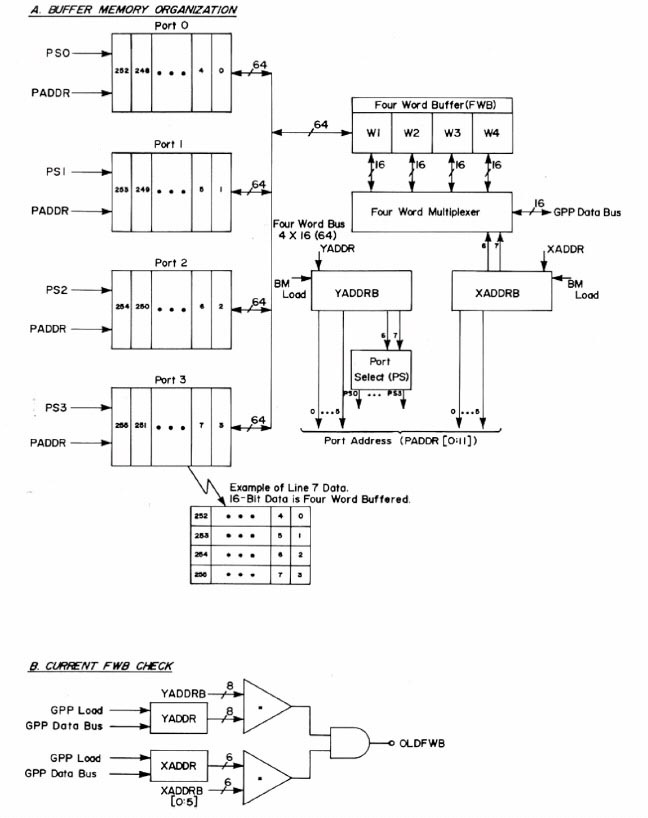
Figure 11. The RTPP buffer memory control logic (reproduced with permission from J. Histochem. Cytochem. [4], 1974). "Each buffer memory is an asynchronous device that received I/O requests either from the general picture process (GPP) or the Quantimet for input or output. Given a request and an address, it first checked to see whether the last (high order 14-bit address) four-word buffer accessed was the same as that for the current request. If so, it did not have to do another memory (RAM) cycle and the signal OLDBWB signal is 'true'. When a read cycle occurred and a different FWB was needed, it checked to see if the FWB was 'dirtied', in which case it must write it back into the memory before the next current request could be proceed. Being dynamic RAMs, they must be refreshed (logic not shown) so as not to lose the data."