Versions Compared

Key

  • This line was added.
  • This line was removed.
  • Formatting was changed.

...

Div
classusa-grid
Div
classusa-width-one-half

The DECsystem-2020 computerImage Modified

Div
classusa-width-one-half

Figure 3. The Digital Equipment Corporation DECsystem-2020 exit disclaimer running the TOPS-10 exit disclaimer operating system. The system is shown with Bruce Shapiro, holding a removable 180MB "bathtub" size disk pack (on the left), and Peter Lemkin (on the right). It had 512K words, 36-bits/word, 256K word virtual space/user, a very powerful instruction set, and many high-level computer languages, including SAIL (Stanford Artificial Intelligence Language - see wikipedia.org entry on SAILexit disclaimer, that made implementing complex analysis algorithms much easier than on the PDP8e. SAIL was developed by Dan Swinehart and Bob Sproull of the Stanford AI Lab exit disclaimer in 1970. Sproull was at Division of Computer Research and Technology (DCRT) in the early 1970s and introduced the language to DCRT [the precursor of NIH's Center for Information Technology (CIT)]. Over time, we implemented more of the advanced image processing and pattern recognition algorithms in SAIL, using the RTPP as a sophisticated data acquisition and interactive graphics front-end. Later many of these algorithms were rewritten in C and UNIX using X-windows (we rewrote the C/UNIX/X-windows GELLAB-II exit disclaimer exploratory analysis system from the SAIL/TOPS-10/RTPP GELLAB-I), and in LISP (StructureLab with a Symbolics Lisp machine and later a Unix Platform) when the DECsystem-10/20 computer lines were phased out in favor of the VAX exit disclaimercomputer lines. Later still, much of the C code for GELLAB-II was converted and rewritten in Java and used as part of the Open2Dprot exit disclaimer project. We will discuss some of these projects later under the section Applications of the RTPP in Biomedical Research.

...

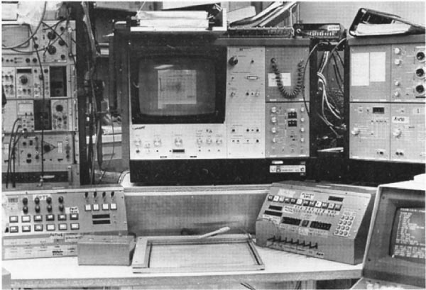
Some of the design details were unique to the Real Time Picture Processor at that era of computer designs. A few of these are illustrated in the following figures. The design is explained in more detail in references [34] and in technical reports [TR-7TR-7aTR-23]. Figures 4 and 5 show block diagrams of the components of the system. Figures 6 and 7 show the interactive control desk that the operator used to interact with the PDP8e and thus the RTPP.RTPP block diagram from original design paperImage Removed

Div
Div
classusa-width-one-half

RTPP block diagram from original design paperImage Added

Div
classusa-width-one-half

Figure 4. The Real Time Picture Processor (RTPP) block diagram (reproduced with permission, from J. Histochem. Cytochem. [4], 1974). This shows additional parts of the system including a PDP11/20 message switcher to a PDP-10 Artificial Intelligence system PRDL (PRocedural Description Language) [5TR-15] originally being developed on NIH's DCRT (now CIT) PDP-10 facility. The early microscope also had a 1024x1024 8-bit galvanometer scanner that could be used in place of the Quantimet 720 scanner. The later microscope was built around a Zeiss Axiomat microscope. An early high-quality grayscale display (Dicomed 31) was also used to make high-quality display images. Its functionality was replaced by the Quantimet grayscale buffer-memory display. The PDP8e accessed the RTPP using the BMON2 software [40TR-21b]. The PDP-10 multiprocessor KL-10 system was a shared time-share computer at DCRT (now CIT). This was replaced in our design by a dedicated DECsystem-2020 when it became more cost-effective to have a dedicated computer. The DECsystem-2020 was a new microcoded processor that DEC was able to build for a fraction of the cost of the PDP-10. The PRDL [TR-15] and PROC10 [TR-8] image processing software were created to interface with the RTPP. We had considered creating a MAINSAIL(R) exit disclaimerImage Modified compiler for use with the GPPASM (GPP assembler program) [TR-16] so that we could program the GPP in a SAIL-like language only available on large PDP-10 class systems. Later, a light box for films was used with the Quantimet vidicon scanner (see Figure 18) with changeable 35mm lenses (not shown in this block diagram - see Figure 5) to scan autoradiograph and wet 2D gels, RNA electron micrographs, and other transparencies.

...

Div
Div
classusa-width-one-half

RTPP block diagramImage Added

Div
classusa-width-one-half

Figure 5. A simplified block diagram of the Real Time Picture Processor illustrating the two types of input and the microscope control from BMON2 paper [40], 1980. (Reprinted from Computer Programs in Biomedicine, vol 11, Lemkin P., Lipkin, L., BMON2 - A distributed monitor system for biological image processing, pp 21-42, Copyright (1980), with permission from Elsevier.) The PDP8e computer directed the microscope stage to positions determined either manually by the operator or by a list of positions defined by the user and then controlled by the computer. Images could be acquired by the buffer memories for processing by the BMON2 system. Raw images as well as processed images could be displayed on the Quantimet 720 CRT display. TV camera input was from either of the two TV cameras that were easily changed. The user interacted with the hardware using the control panel connected to the PDP8e using the BMON2 image processing software system.

...

Div
Div
classusa-width-one-half

RTPP control console connected to PDP8e and controlling the RTPPImage Added

Div
classusa-width-one-half

...

Figure 6. RTPP Control Console was interfaced to the PDP8e and used to interact with the RTPP using the BMON2 buffer memory monitor operating system [40TR-21TR-21b]. See Figure 2 in [TR-21b] for the full description. It had various knobs (connected to A/D converters read by the PDP8e), lights for feedback, command buttons, toggle switches, and momentary toggle switches. Only some of these controls were used in the various programs, but having a variety of control options providing flexibility in the user interface. However, this was sometimes at the cost of added complexity and sometimes users had difficulty in learning the system because of this. ("All those knobs, buttons and switches!") However, this flexibility gave us the option of experimenting with various interaction modes that could then be optimized for particular analysis programs. This was before the computer mouse and graphical user interfaces became commonly available. (Click on this figure to bring up the high-resolution version of the figure. You may have to make your browser window larger.)

...

Div
Div
classusa-width-one-half

RTPP Quantimet-TV and control-console control the RTPP through the PDP8eImage Added

Div
classusa-width-one-half

Figure 6. RTPP Control Console was interfaced to the PDP8e and used to interact with the RTPP using the BMON2 buffer memory monitor operating system [40TR-21TR-21b]. See Figure 2 in [TR-21b] for the full description. It had various knobs (connected to A/D converters read by the PDP8e), lights for feedback, command buttons, toggle switches, and momentary toggle switches. Only some of these controls were used in the various programs, but having a variety of control options providing flexibility in the user interface. However, this was sometimes at the cost of added complexity and sometimes users had difficulty in learning the system because of this. ("All those knobs, buttons and switches!") However, this flexibility gave us the option of experimenting with various interaction modes that could then be optimized for particular analysis programs. This was before the computer mouse and graphical user interfaces became commonly available. (Click on this figure to bring up the high-resolution version of the figure. You may have to make your browser window larger.)

Div
Div
classusa-width-one-half

RTPP Quantimet-TV and control-console control the RTPP through the PDP8eImage Added

Div
classusa-width-one-half

...

Figure 7. Photograph of the Quantimet-TV and control-console for the RTPP using the BMON2 software [40TR-21TR-21bTR-23]. This was taken after we had moved the RTPP to the Park Building in Rockville, MD. (Reproduced from a figure with permission from Environmental Health Perspectives, 1980 []). The control desk had a microscope joystick (X,Y) and Z-axis (focus) control; knobs (connected to A/D converters read by the PDP8e), switches and lights that could be configured in various ways by the BMON2 software. The small box shown in the lower left allowed us to control the 4 edges of a frame as (X,Y) positions. It used four bi-directional two-level spring-loaded switches in a (North, South, East, or West) configuration. These switches came from the LINC-8 and were perfect for this type of control. This allowed us to easily control the direction of a cursor - much as is done today using the mouse, which did not exist at the time). Real-time video control was performed using the RTPP buffer memory controller hardware, which in turn was configured by the PDP8e. The control desk gave us a lot of flexibility - even if its complexity was sometimes compared to that of the starship Enterprise. Various programs (BMON2, FLICKER [13], LANDMARK in the GELLAB-I system [151731], and others) could use that subset of the controls most appropriate for the particular application.


The buffer memory image cards

...