Versions Compared

Key

  • This line was added.
  • This line was removed.
  • Formatting was changed.

...

  • Lewis Lipkin: optical microscopy of serial brain sections and macrophage motility measurements with asbestos
  • Peter Lemkin: bone marrow smear analysis, 2D gel electrophoresis
  • Bruce Shapiro: RNA secondary structure of electron micrograph
  • Carl Merril: NIMH/NIH - 2-dimensional (2D) gel electrophoresis, E.coli mutants and macrophages with asbestos
  • Jacob Maizel: NICHD/NIH, with Bruce Shapiro - RNA electron microscopy of secondary structure
  • Eric Lester: NCI, U. Chicago, and oncology practice - 2D gel electrophoresis on human leukemia
  • Steve Aley and Russell Howard: NIAID/NIH - 2D gel electrophoresis of Plasmodium knowlesi clones
  • Peter Wirth and Snorri Thorgeirsson: NCI/NIH - 2D gel electrophoresis on liver cell lines
  • Peter Sonderegger: NICHD/NIH and U. Zurich - 2D gel electrophoresis of axonal proteins of sensory and motor neurons


Div
classgrid-row grid-gap
Div
classdesktop:grid-col-6

The 'mcrew' picture taken when RTPP was first running

Div
classdesktop:grid-col-6

Figure 2. One of the first images taken using the RTPP was of the development group just after we got the Digital Equipment Corporation DECsystem-2020 interface to the RTPP buffer memory working. The image was one we called "mcrew" (i.e., 'machine crew'). Top row (L-R): Dan Kilgore, George Carman, and Morton Schultz. Bottom row (L-R): Earl Smith and Peter Lemkin. Not shown: Bruce Shapiro and Lew Lipkin who were integral parts of the RTPP design and development team.

Div
classgrid-row grid-gap
Div
classdesktop:grid-col-6

The DECsystem-2020 computer

Div
classdesktop:grid-col-6

Figure 3. The Digital Equipment Corporation DECsystem-2020 exit disclaimer running the TOPS-10 exit disclaimeroperating system. The system is shown with Bruce Shapiro, holding a removable 180MB "bathtub" size disk pack (on the left), and Peter Lemkin (on the right). It had 512K words, 36-bits/word, 256K word virtual space/user, a very powerful instruction set, and many high-level computer languages, including SAIL (Stanford Artificial Intelligence Language - see wikipedia.org entry on SAILexit disclaimer, that made implementing complex analysis algorithms much easier than on the PDP8e. SAIL was developed by Dan Swinehart and Bob Sproull of the Stanford AI Lab exit disclaimer in 1970. Sproull was at Division of Computer Research and Technology (DCRT) in the early 1970s and introduced the language to DCRT [the precursor of NIH's Center for Information Technology (CIT)]. Over time, we implemented more of the advanced image processing and pattern recognition algorithms in SAIL, using the RTPP as a sophisticated data acquisition and interactive graphics front-end. Later many of these algorithms were rewritten in C and UNIX using X-windows (we rewrote the C/UNIX/X-windows GELLAB-II exit disclaimer exploratory analysis system from the SAIL/TOPS-10/RTPP GELLAB-I), and in LISP (StructureLab with a Symbolics Lisp machine and later a Unix Platform) when the DECsystem-10/20 computer lines were phased out in favor of the VAX exit disclaimercomputer lines. Later still, much of the C code for GELLAB-II was converted and rewritten in Java and used as part of the Open2Dprot exit disclaimer project. We will discuss some of these projects later under the section Applications of the RTPP in Biomedical Research.

...

Anchor
RTPP-Quantimet-PDP8e-blockDiagram-CarmIIpaper

Div
classgrid-row grid-gap
Div
classdesktop:grid-col-6

RTPP block diagram from original design paper

Div
classdesktop:grid-col-6

Figure 4. The Real Time Picture Processor (RTPP) block diagram (reproduced with permission, from J. Histochem. Cytochem. [4], 1974). This shows additional parts of the system including a PDP11/20 message switcher to a PDP-10 Artificial Intelligence system PRDL (PRocedural Description Language) [5TR-15] originally being developed on NIH's DCRT (now CIT) PDP-10 facility. The early microscope also had a 1024x1024 8-bit galvanometer scanner that could be used in place of the Quantimet 720 scanner. The later microscope was built around a Zeiss Axiomat microscope. An early high-quality grayscale display (Dicomed 31) was also used to make high-quality display images. Its functionality was replaced by the Quantimet grayscale buffer-memory display. The PDP8e accessed the RTPP using the BMON2 software [40TR-21b]. The PDP-10 multiprocessor KL-10 system was a shared time-share computer at DCRT (now CIT). This was replaced in our design by a dedicated DECsystem-2020 when it became more cost-effective to have a dedicated computer. The DECsystem-2020 was a new microcoded processor that DEC was able to build for a fraction of the cost of the PDP-10. The PRDL [TR-15] and PROC10 [TR-8] image processing software were created to interface with the RTPP. We had considered creating a MAINSAIL(R)exit disclaimer compiler for use with the GPPASM (GPP assembler program) [TR-16] so that we could program the GPP in a SAIL-like language only available on large PDP-10 class systems. Later, a light box for films was used with the Quantimet vidicon scanner (see Figure 18) with changeable 35mm lenses (not shown in this block diagram - see Figure 5) to scan autoradiograph and wet 2D gels, RNA electron micrographs, and other transparencies.


Anchor
RTPP-Quantimet-PDP8e-blockDiagram


Div
classgrid-row grid-gap
Div
classdesktop:grid-col-6

RTPP block diagram

Div
classdesktop:grid-col-6

Figure 5. A simplified block diagram of the Real Time Picture Processor illustrating the two types of input and the microscope control from BMON2 paper [40], 1980. (Reprinted from Computer Programs in Biomedicine, vol 11, Lemkin P., Lipkin, L., BMON2 - A distributed monitor system for biological image processing, pp 21-42, Copyright (1980), with permission from Elsevier.) The PDP8e computer directed the microscope stage to positions determined either manually by the operator or by a list of positions defined by the user and then controlled by the computer. Images could be acquired by the buffer memories for processing by the BMON2 system. Raw images as well as processed images could be displayed on the Quantimet 720 CRT display. TV camera input was from either of the two TV cameras that were easily changed. The user interacted with the hardware using the control panel connected to the PDP8e using the BMON2 image processing software system.

...

Anchor
ControlDesk
ControlDesk


Div
classgrid-row grid-gap
Div
classdesktop:grid-col-6

RTPP control console connected to PDP8e and controlling the RTPP

Div
classdesktop:grid-col-6

Figure 6. RTPP Control Console was interfaced to the PDP8e and used to interact with the RTPP using the BMON2 buffer memory monitor operating system [40TR-21TR-21b]. See Figure 2 in [TR-21b] for the full description. It had various knobs (connected to A/D converters read by the PDP8e), lights for feedback, command buttons, toggle switches, and momentary toggle switches. Only some of these controls were used in the various programs, but having a variety of control options providing flexibility in the user interface. However, this was sometimes at the cost of added complexity and sometimes users had difficulty in learning the system because of this. ("All those knobs, buttons and switches!") However, this flexibility gave us the option of experimenting with various interaction modes that could then be optimized for particular analysis programs. This was before the computer mouse and graphical user interfaces became commonly available. (Click on this figure to bring up the high-resolution version of the figure. You may have to make your browser window larger.)

...

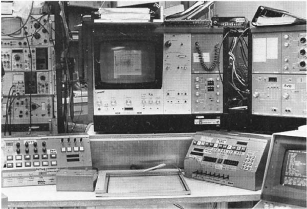
Anchor
PhotoRTPPandConsole
PhotoRTPPandConsole


Div
classgrid-row grid-gap
Div
classdesktop:grid-col-6

RTPP Quantimet-TV and control-console control the RTPP through the PDP8e

Div
classdesktop:grid-col-6

Figure 7. Photograph of the Quantimet-TV and control-console for the RTPP using the BMON2 software [40TR-21TR-21bTR-23]. This was taken after we had moved the RTPP to the Park Building in Rockville, MD. (Reproduced from a figure with permission from Environmental Health Perspectives, 1980 []). The control desk had a microscope joystick (X,Y) and Z-axis (focus) control; knobs (connected to A/D converters read by the PDP8e), switches and lights that could be configured in various ways by the BMON2 software. The small box shown in the lower left allowed us to control the 4 edges of a frame as (X,Y) positions. It used four bi-directional two-level spring-loaded switches in a (North, South, East, or West) configuration. These switches came from the LINC-8 and were perfect for this type of control. This allowed us to easily control the direction of a cursor - much as is done today using the mouse, which did not exist at the time). Real-time video control was performed using the RTPP buffer memory controller hardware, which in turn was configured by the PDP8e. The control desk gave us a lot of flexibility - even if its complexity was sometimes compared to that of the starship Enterprise. Various programs (BMON2, FLICKER [13], LANDMARK in the GELLAB-I system [151731], and others) could use that subset of the controls most appropriate for the particular application.

...

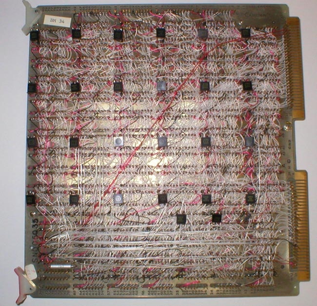
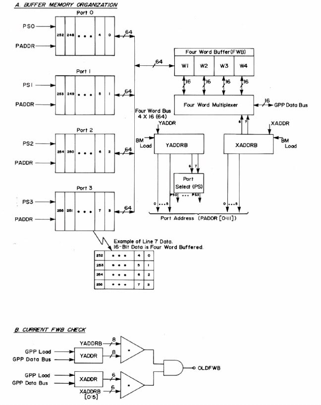
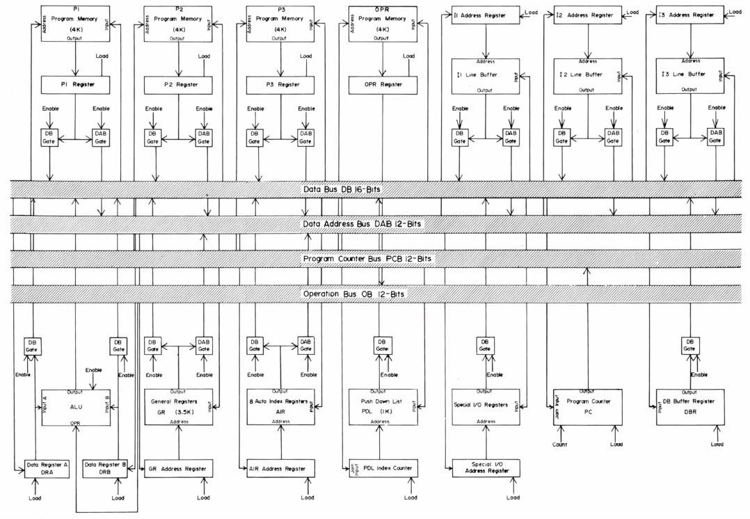
During this time, we had the conviction, led by Lew Lipkin and George Carman, that anything that we wanted to be do in software could be done by a series of sequential gates. These could be proved Boolean algebraically correct using Karnaugh Mapsexit disclaimer, hardware finite state machines, and related techniques. George had just taken a microprogramming design course as part of his masters degree in computer hardware architecture and the design of buffer memories and the General Picture Processor (GPP) were perfect test beds in which to try out these new design principles which were relatively new for projects like this. Some of the design diagrams are shown in Figures 11 through 14 (from the Carman [4] paper). Figure 15 shows some examples of GPP microprogrammed instructions for manipulating the buffer memory data. The design was further described in some of the technical reports [TR-7TR-7aTR-16TR-21TR-21bTR-22] listed at the end of this history. Because we were prototyping the system, the card was constructed using wire wrapping rather than multilayer printed circuit boards. A commercial version would have used printed circuit boards, but would only have been economically feasible if many copies of the RTPP were produced. Using complex multi-level printed circuit boards is generally too expensive for a research lab. 

Anchor
BufferMemoryBoard
BufferMemoryBoard

Div
classgrid-row grid-gap
Div
classdesktop:grid-col-6

Front of a buffer memory image card

Div
classdesktop:grid-col-6

Figure 8. Front of a buffer memory image card containing 64Kb x 16-bits of dynamic RAM constructed from 4Kx1 bit dynamic RAM chips (Texas Instruments part number TMS 4030) initially sold by Texas Instruments and later second-sourced by National Semiconductor and Signetics. Four boards constituted a 256x256x16-bit pixel sub-image. Either the high or low 8-bit byte (or neither) could be displayed. Each 256x256 sub-image could be positioned to any part of the 860x720 pixel TV screen. For many applications, to create a 512x512 image, four 256x256 sub-images were grouped to form a 512x512 image.

...

Anchor
TMS4030chip
TMS4030chip

Div
classgrid-row grid-gap
Div
classdesktop:grid-col-6

The 4Kx1bit Texas Instruments TMS 4030 dynamic RAM memory chip

Div
classdesktop:grid-col-6

Figure 9. The 4Kx1 bit dynamic RAM or DRAM chip (part number TMS 4030) initially sold by Texas Instruments and second sourced by National Semiconductor, and Signetics (shown here). These were the first affordable (about $20 at the time) DRAMs available in large quantitities. Because chip vendors want to assure customers that the parts will always be available, they license other chip makers to "second source" interchangeable chips. Our memory boards are a mix of the black, silver, and gold colored chips because we used several vendors.

Div
classgrid-row grid-gap
Div
classdesktop:grid-col-6

Back of a buffer memory image card

Div
classdesktop:grid-col-6

Figure 10. Back of a buffer memory image card containing 64Kb x 16-bits of dynamic RAM constructed from 4Kx1 bit dynamic RAM (part number TMS 4030) chips initially sold by Texas Instruments and second sourced by National Semiconductor and Signetics. There were over 3,000 wirewraps on each board. The initial card was designed and hand wired by George Carman, and Cambion Corporation replicated 63 additional cards with wirewrap wiring lists generated by George. Their automatic robots would position the board for each of the wrap positions and then wire that point. The photograph illustrates how easy it is to get lost in this forest of pins and wires. Doing this by hand would have been impossible. George felt that no other company could build the boards in the time frame with the essential quality control we required. He was right. Only one of the 63 the boards delivered was defective, which was amazing considering the complexity and number of boards. Because of the high frequency signals involved, George put small black decoupling capacitors on each board to "tune" it to minimize cross talk. So each board, then, was in some sense unique.

Anchor
Fig-RTPP-BufferMemory-control-logic

Div
classgrid-row grid-gap
Div
classdesktop:grid-col-6

RTPP buffer memory control logic

Div
classdesktop:grid-col-6

Figure 11. The RTPP buffer memory control logic (reproduced with permission from J. Histochem. Cytochem. [4], 1974). "Each buffer memory is an asynchronous device that received I/O requests either from the general picture process (GPP) or the Quantimet for input or output. Given a request and an address, it first checked to see whether the last (high order 14-bit address) four-word buffer accessed was the same as that for the current request. If so, it did not have to do another memory (RAM) cycle and the signal OLDBWB signal is 'true'. When a read cycle occurred and a different FWB was needed, it checked to see if the FWB was 'dirtied', in which case it must write it back into the memory before the next current request could be proceed. Being dynamic RAMs, they must be refreshed (logic not shown) so as not to lose the data."

Anchor
Fig-RTPP-GPP-bus-structure

Div
classgrid-row grid-gap
Div
classdesktop:grid-col-6

RTPP general picture processor (GPP) bus structure

Div
classdesktop:grid-col-6

Figure 12. The RTPP general picture processor (GPP) bus structure (reproduced with permission from J. Histochem. Cytochem. [4], 1974). "The instruction addressing sequence is done serially. That is, Pi is addressed, then P2, then P3. Let 'c(.)' denote 'contents of current memory location'. If any address is immediate, no memory fetch is done. Rather, the PM data, c(P), is enabled onto the data bus DB. If direct addressing mode c(c(P)) is used, the PM data c(P) is enabled onto the data address bus, DAB, and then loaded onto the appropriate data field address register. The memory then enables its data, c(c(P)), onto the data base, DB. If indirect mode is used then the same sequence is repeated as for direct mode, but c(c(P)) is enabled back onto the DAB instead of the DB. Then the data address field register addressed is loaded and the c(c(c(P))) from that memory is enabled onto the DB. A conflict may occur in the use of the indirect mode from the 'MOVE' instruction. This is resolved by storing the source data in the data bus register, DBR, temporarily. Various devices and memories are connected to the bus structure and interact when the control section activates them. The average GPP instruction time is designed to be on the order of 250 nanoseconds." (Click on this figure to bring up the high-resolution version of the figure. You may have to make your browser window larger.)

Div
classgrid-row grid-gap
Div
classdesktop:grid-col-6

RTPP triple line buffer logic

Div
classdesktop:grid-col-6

Figure 13. The RTPP triple line buffer logic (reproduced with permission from J. Histochem. Cytochem. [4], 1974). "The RTPP was designed to do 3x3 neighborhood image-processing in parallel in the GPP. Associated with the three lines is an effective Y dynamic address used to order the three lines as to (Y-1,Y,Y+1). In reading a raster line pattern into the triple line buffer, the oldest line must be replaced with the newest line. Similarly, the other two lines need to be adjusted as (Y-1,Y,Y+1) to (Y,Y+1,Y+2). By selecting the effective line address with a modulo three dynamic Y address counter, a dynamic Y address can be implemented. This is similar to the concept of buffer. The three X dynamic address vectors point to 3x3 neighborhood arrays in the line buffer. This neighborhood is called the current neighborhood. All of the dynamic address vectors are easily and efficiently programmed in the GPP to tessellate the current neighborhood along the three lines in the line buffer."

...